|
| | | |
?

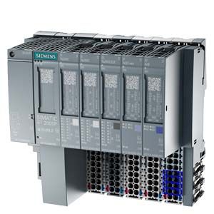
ET 200SP for SIMATIC PCS 7, design
Main components of the SIMATIC ET 200SP distributed I/O system
- IM 155-6PN High Feature interface module
with bus adapter (removable part for definition of connection system: BA 2xRJ45 or BA 2xFC) for communication with the SIMATIC PCS 7 automation system (controller) via PROFINET IO
- I/O modules
4, 8 or 16 digital channels (DI, DQ, RQ) and 4 analog channels (AI, AQ); up to 64 I/O modules can be plugged in any combination onto passive BaseUnits
- BaseUnits
Supports for the plug-in I/O modules and the terminal box; for construction of the backplane bus and for the mechanical/electrical connections
- Server module
for connection of ET 200SP station
- Standard mounting rail
for latching-in of interface module, BaseUnits and server module; for installation of ET 200SP station in control cabinet
The extremely compact design allows a high packing density. With a depth of approx. 75 mm, the overall height is e.g.:
- 117 mm with 16 channels and 1?wire connection (without AUX terminals)
- 141 mm with 8 channels and 3?wire connection and AUX terminals
Replaceable bus adapters enable free selection of the PROFINET connection system from the following versions:
- BA 2?RJ45: Connection via standard RJ45 connectors
- BA 2?FC: Large-area shielded connection of bus cables; resistant to vibrations and high EMC loads
The BaseUnits mounted on a standard rail can already be wired and tested prior to connection of the I/O modules (permanent wiring).
Hot swapping of the I/O modules and terminal boxes plugged onto the BaseUnits is possible. Mechanical coding prevents the use of an incorrect slot and the resulting destruction of the module electronics.
A BU cover is available for reserved, unequipped slots (BaseUnit without I/O module) as protection for the BaseUnit connectors. It can be provided with a reference ID label.
For the connection of cable shields that is both space-saving as well as optimized in terms of EMC, a shield connection is available that is quick and easy to mount. This consists of a shield connection element that can be plugged onto the BaseUnit and a shield terminal.
An inscription and color identification system with the following components facilitates orientation:
- Labeling strips for insertion in interface and I/O modules
- Color-coded labels for cable assignment and identification of the potentials of an I/O module
- Reference ID labels for identification of system components
Installation
Installation of an ET 200SP station is quick and easy:
- Latching-in of interface module, BaseUnits and server module on a standard mounting rail (35 x 15 x 7.5 mm or 35 x 15 x 15 mm)
- Connection of the cables for the 24 V DC power supply on the interface module
- Plugging-on and screwing tight of the bus adapter
- Prewiring of the 24 V DC power supply and process signal cables on the BaseUnits
- Plugging-on of the I/O modules
The ET 200SP station can be installed in any orientation. However, the first choice is horizontal installation in enclosures or control cabinets.
Configuration limits and guidelines
- Up to 64 I/O modules (digital/analog) with a data volume of up to 1440 bytes; up to 1024 signals
- A light BaseUnit must always be configured as the first BaseUnit of an ET 200SP station.
- The thermal continuous current for the load or encoder supply can be a maximum of 10 A per potential group.
- The I/O modules can be mixed in any manner within a load group.
|
